Abstract: The structural optimization design of the flange fork, spline shaft fork and universal joint fork and other parts of heavy-duty automobile driveshaft is carried out.
First of all, the three-dimensional model of the parts is established in Creo software, and the structural static analysis is carried out using ANSYS Workbench software, which obtains that the dangerous cross section is consistent with the part of the fracture occurred in the actual application, and the quality of the model matches with the weighing of the real object, so as to complete the calibration of the three-dimensionamodel.
Then the structural topology optimization analysis of the model was carried out by using the variable density method, and according to the analysis results, its structural shape was eliminated and size optimization was carried out, and the optimized parts were calibrated.
The results show that the application of topology optimization design method can effectively reduce the quality of parts and achieve the goal of lightweight design of automotive driveshaft.
Keywords: driveshaft; topology optimization; lightweight design; Ansys
1 Introduction
As resources and the environment are becoming increasingly severe, reducing automobile fuel consumption through lightweight design is not only environmentally friendly and energy-saving, but also the development trend of the entire automobile industry.
Transmission shaft is an important component for transmitting power in the process of automobile operation, which is a rotating body with high speed and little support, and its own moment of inertia in the process of high-speed rotation has a greater impact on the transmission efficiency and vibration of the whole shaft, and the mass is a key factor in determining the moment of inertia .
Therefore, its lightweight design is of great significance:
- Establishes the equations of motion of duplexed Hooke universal joints, and analyzes the influence of the inter-axis angle and phase angle on the rotational angle difference and instantaneous transmission ratio.
- Used fishbone diagram to analyze the cause of fracture of the flange fork of the drive shaft, and carried out structural optimization and finite element analysis.
- Used topology optimization method to design the wall thickness of the rotating shaft by thinning.
- Studied the correspondence between the design stress distribution interval and the low load strengthening characteristic interval of the drive shaft, and used this to obtain the structural parameters to realize the lightweight design of the drive shaft.
- Carried out a comparative analysis of the performance of two new composite materials, replaced the key parts of the drive shaft materials, and combined with the actual engineering for the calibration.
- The above research has optimized the design of automotive driveshafts from the mechanical structure and material aspects, and achieved good research results, but due to the lack of complete lightweight design theory and strict manufacturing system, the domestic driveshafts, compared with similar foreign products, there is still a large space for improvement in terms of weight, reliability and fatigue strength.
Therefore, it is of great significance to study the lightweight design method of automobile driveshaft, and to carry out topology optimization and reliability analysis of its structure in the lightweight design of automobile.
2 Driveshaft/Propshaft lightweight design methods
At this stage, there are three main methods for lightweight design:
(1) structural optimization, i.e., through the secondary design of the structure of each part of the driveshaft, make the parts thin-walled and hollow, and use CAD/CAE/CAM and other digital design and manufacturing methods to achieve the purpose of lightweight;
(2) the use of advanced manufacturing processes, such as laser cutting, laser welding, hydraulic forming, etc., to improve the accuracy of manufacturing, and realize the lightweight of the parts;
(3) the use of high-strength lightweight materials, such as magnesium, aluminum and its alloys, etc., to achieve the purpose of lightweight by replacing the traditional materials with materials of the same strength but smaller quality.
The first method, i.e. structural optimization, is mainly used to study the lightweight design method of transmission shaft.
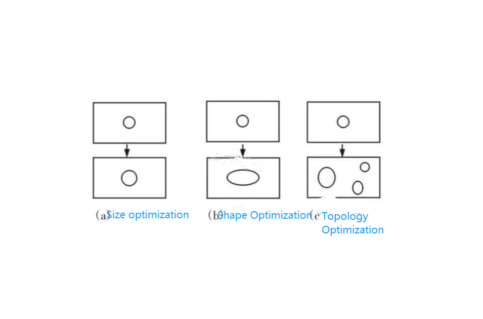
Structure optimization can be divided into size optimization, shape optimization and topology optimization.
Dimension optimization is to parameterize the floating dimensions, and after setting the floating range, the dimensions are arranged and combined, and then select the optimal solution; shape optimization is to take the shape structure of the material as the optimization direction, and try to make the shape as beautiful as possible under the circumstance of reducing the weight; topology optimization is to optimize the arrangement of the product material in a certain range, and after comparing multiple optimization solutions, the optimal solution is finally determined.
Topology Optimization From the above analysis, it can be seen that the topology optimization scheme is equivalent to the combination of the previous schemes, which has a wider range of applications. The differences of the three optimization types are shown in Fig. 1.
Topological optimization is a mathematical method to optimize the material distribution within a certain interval according to the given conditions such as load conditions, constraints and related parameters.
According to the different structural forms of the object, topology optimization can be divided into two kinds: one is to discretize the overall material, that is, the required material is scattered into a finite number of units, and then add up each unit; the other is to continuous material, that is, the whole is divided into a finite number of units, based on the internal algorithm of the finite element to determine the retention and removal of these units, and distinguish them with different colors, and according to the results of simulation analysis Combined with practical application experience, the part that is finally retained is the final optimization scheme.
The commonly used methods for topology optimization include homogenization method, variable density method, variable thickness method, independent continuous mapping model method, level set method, etc., among which variable density method is one of the most representative methods.
The variable density method is developed on the basis of the homogenization method, which discretizes the continuum into a finite element model, takes the relative density of the structural unit as the design variable, and artificially assumes that there is some kind of functional relationship between the density of the unit and the macroscopic physical properties of the material.
Where the relative density of the unit is a pseudo-density reflecting the correspondence between the density of the material and the material properties, and the size varies in the interval [0, 1].
The variable density method can be used not only for the optimization of structural flexibility, but also for the optimization of other characteristic values by establishing different objective functions.
The mathematical model of the variable density method can be expressed in the following form:

Where: xi-design variable, representing the relative density of discrete units;
C(x)-objective function, representing the flexibility of the structure;
F-vector of external forces on the structure;
n-number of design variables;
U-structure displacement vector;
V-volume of the structure;
V*-upper limit value of the optimized volume;
K-Total stiffness matrix;
xmin-minimum value of the design variables, which is usually taken as 0.001 in order to avoid singularity of the total stiffness matrix.
Topology optimization analysis obtains the optimal solution of the objective function by changing the numerical magnitude of the design variables and then setting the upper and lower limits of the state volume.
ANSYS Workbench finite element analysis software comes with a topology optimization module, and its internal optimization algorithm uses the variable density method.
According to the mathematical model of equation (1), when using ANSYS Workbench for topology optimization, the parameters that need to be defined are the flexibility objective function C (x), the volume constraint function V and the boundary conditions of the model work. The specific solution process is as follows: (1) establish a parametric model; (2) determine the boundary conditions and loading; (3) carry out the static analysis; (4) define the mass as the objective function; (5) define the volume function as the constraint function, and set the volume to be reduced by 60%; (6) determine the optimization method to be the OC method; (7) set the maximum number of iterations of the topology optimization to be 30; and (8) solve the problem and post-processing.
3 Topology Optimization of Drive Shaft Structure
3.1 Analysis of Drive Shaft Structure
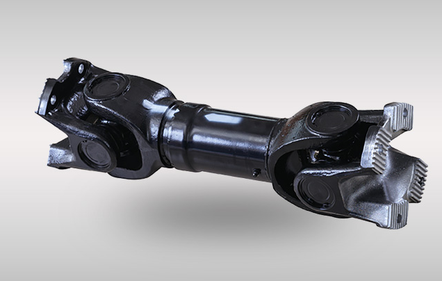
The K57G0 driveshaft is a transmission component used in heavy-duty vehicles, which is mainly composed of two parts: the front driveshaft and the rear driveshaft.
After research, it is found that there is much room for optimization of the rear driveshaft of this driveshaft, so the lightweight design of the rear driveshaft is mainly targeted at the rear driveshaft.
First of all, the three-dimensional model of the rear driveshaft is simplified to improve the efficiency and feasibility of finite element analysis, and the principle of simplification is to remove some small parts with little quality or complex structure, such as needle rollers, threads, gaskets and so on, under the premise of conforming to the practical application.
According to the above principle, the assembly model of the rear drive shaft established in Creo is shown in Figure 2.
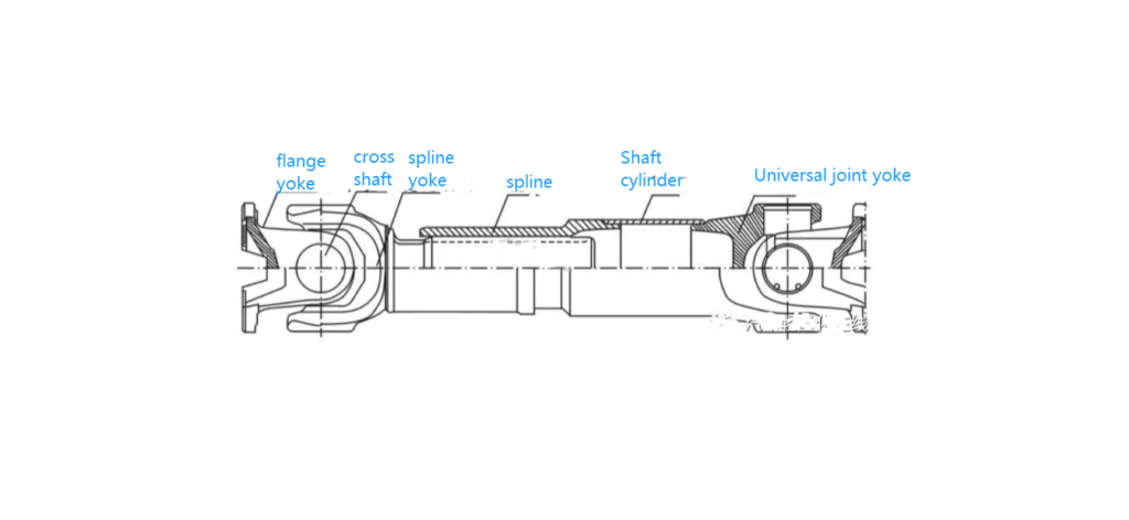
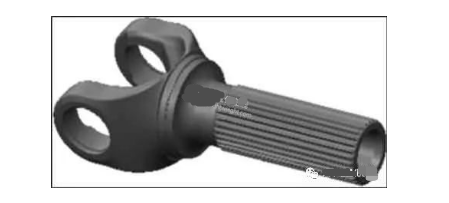
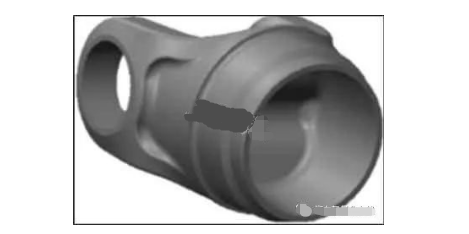
The rear propeller shaft is mainly composed of six parts: universal joint yoke, flange yoke, cross shaft, spline, spline shaft yoke and shaft cylinder, as shown in Fig.2.
After study, it is found that the flange yoke, spline shaft yoke and universal joint yoke of this driveshaft/propshaft are on the heavy side.
Therefore, the lightweight design of the rear driveshaft mainly focuses on the flange yoke, spline yoke and universal joint yoke.
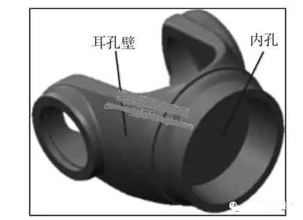
According to the results of topology optimization analysis and a large amount of experimental data in the early stage, it can be seen that: the flange yoke’s two sides of the wall and the center of the stress is small, the material is relatively more, there is a large optimization space; the spline yoke’s maximum stress is concentrated in the journal, and the stress of the teeth is small, so it can be appropriate to reduce the number of teeth and the hollowing of the shaft to reduce the weight; the cardan yoke’s maximum stress is concentrated in the bottom of the trunnion hole wall at the cross-section of the mutation, due to the minimum stress, it can be taken to reduce the material and increase the weight of the trunnion hole wall. Cutting down the material of the ear hole wall and increasing the hollowing of the inner hole to make it lightweight can be optimized parts, as shown in Figure 3 and Figure 6. Since the optimization methods of the three parts are the same, only the flange yoke is discussed as an example.
The simplified cross shaft, flange and flange fork are imported into ANSYS Workbench, and the material parameters are set to 40Cr, modulus of elasticity is 2.11e11Pa, Poisson’s ratio is 0.33, and the yield strength is 785MPa. Since ANSYS Workbench and Creo can realize seamless connection, it can automatically identify each contact pair as Bond. Bond. Using automatic meshing, the number of grid nodes generated is 106853, the number of cells is 53546, and the average coefficient of mesh quality is 0.7, the mesh quality is good, and the subsequent finite element analysis can be carried out accurately. Then the load is applied, and the Moment (torque) load of 24000N-m is applied to both ends of the cross shaft at the unassembled end, and the boundary conditions are set as the flange fixed. Finally, the solution term is set and Total Deformation and Equivalent (von-Mises) are inserted under the solution node, and the results are shown in Fig. 7 and Fig. 8 respectively.
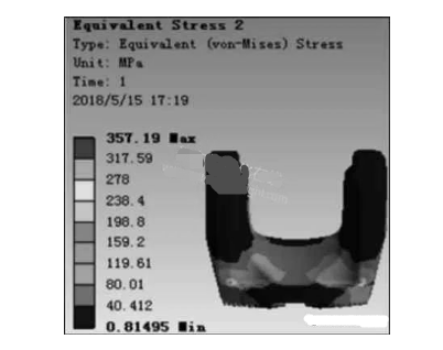
From Fig. 7, it can be seen that the maximum equivalent stress of the flange fork is 357.19MPa, which is concentrated at the junction between the bottom of the ear wall and the flange, which is consistent with the actual fracture site of the flange fork at work.
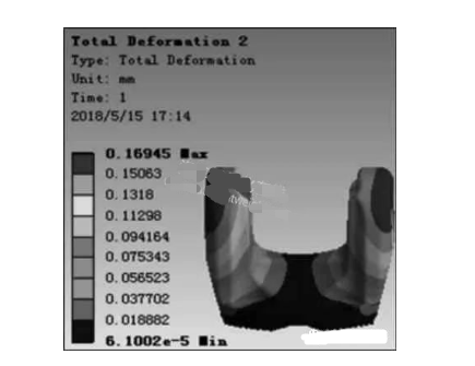
From Fig. 8, it can be seen that the maximum deformation of the flange fork is 0.16945mm, which occurs above the ear holes, this is because the existence of the ear holes makes its material relatively weak compared to other parts, which is consistent with the actual maximum deformation site.
In ANSYS Workbench, the mass of the model is 9.23kg, and the actual weight is 9.24kg, which is basically consistent in terms of weight.
The above points fully demonstrate that the established finite element model is accurate, if the error is large, it is necessary to further correct the finite element model.
3.2 Topology optimization design
On the basis of the above static calculation, the topology optimization analysis of the flange fork is carried out.
Firstly, the Shape Optimization module in ANSYS Workbench is added into the static analysis model, and then the same loads and constraints as those of the static analysis are applied, and the Target Reduction is set to 60% in the Shape Finder window, i.e., the target of the topology optimization is to reduce the volume V by 60%, and then the optimization criterion is set to define the iterations.
Optimization criterion, define the number of iterations as 30 times, the analysis results, as shown in Figure 9.
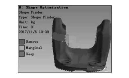
In Fig.9 one color is reserved area and other color is removable area.
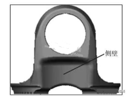
According to the optimizable areas given by Workbench, it can be seen that the material utilization of the center, side walls and tine grooves of the flange fork is low, so the material of these areas can be reduced appropriately.
In addition, in the design process, we should also consider the stress concentration phenomenon brought by the reduction of material on the other uncut parts.
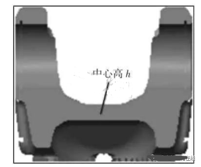
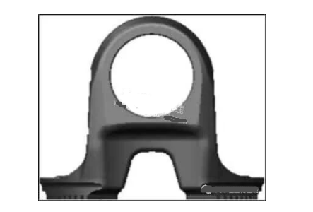
Since the actual product has less material in the connection part of the tines and grooves, the center height of the flange fork and the two side walls are optimized by taking into consideration the cost of processing and manufacturing as well as the aesthetics of the product, as shown in Figs. 3 and 4.
In the conceptual design stage, the results of shape topology optimization analysis can be used to guide the shape design of the product, but when applied to the actual engineering, the results cannot be directly applied to the actual engineering due to the complex working conditions that cannot be completely simulated.
This optimization design combines the practical engineering experience and proposes an optimization scheme for the two side walls of the flange fork, as shown in Fig. 10.
The design takes into account the stress condition of the side wall and the manufacturing process, and adopts the design principle of small top and large bottom, designing a trapezoidal section with rounded corners on both sides of the original model, and the parameters such as top bottom, bottom bottom and height of the trapezoidal section are analyzed through a large number of simulations, and it is found that when the three parameters are 30mm, 52mm and 32mm, the maximal stress is 359.79MPa,
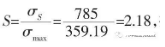
and the safety coefficient is close to the first optimization design safety coefficient of 2.5MPa, which is close to that of the first optimization design.
Close to the first step of the optimization design safety factor of 2.15, and the lower bottom edge size parameters have less impact on the stress, so according to the location of the flange teeth to choose the maximum lower bottom edge of 52mm, the upper bottom edge and the height of the size of the parameters of the variable analysis method, with a, b, h, respectively, trapezoidal upper and lower bottom edges and high, respectively, the maximum stress and deformation of the parts were expressed in terms of σmax and ΔL, the analysis of the data, as shown in Table 1.
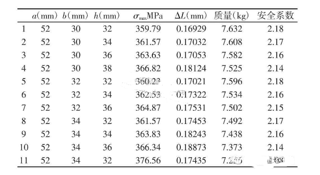
As shown in Table 1, when the bottom, top and height of the trapezoidal section are 52mm, 34mm and 34mm respectively, the mass is 7.438kg, which is 1.792kg lower than that before optimization; the maximum stress is 363.83MPa, which is 357.19MPa higher than that before optimization; but the safety coefficient is larger than the design safety coefficient, which is still within the safety range of the material.
The total deformation of the model is 0.18243mm, which is almost the same as before optimization. In summary, the optimized design of the side walls meets the expected requirements.
After completing the optimization of the two side walls of the flange fork, its center height is then optimized.
Since the flange fork center height dimension can be parameterized, which meets the requirement of parametric design in ANSYS Workbench, the center height is set as a design variable Xi in the pre-processing module, so that the P symbol is displayed in front of it.
After completing the static analysis, the mass, maximum stress and maximum deformation of the model are set as the objective function C(x), the boundary conditions of the design variables are set to 5mm≤h≤16mm, and the Screening method is selected for optimization.
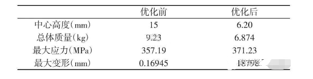
As shown in Table 2, after the optimization of the flange fork’s sidewall and center height, the center height decreases from 15mm before optimization to 6.2mm, and the mass decreases from 9.23kg before optimization to 6.874kg after optimization, which is a weight reduction of 2.356kg; the maximum equivalent stress increases from 357.19MPa before optimization to 371.23MPa, and the coefficient of safety is still greater than 2, which is within the safe design range.
Although the stress increases, the safety factor is still greater than 2, which is within the safe design range, and the total deformation also meets the expected goal.
Using the same method, other components of the drive shaft were topologically optimized.
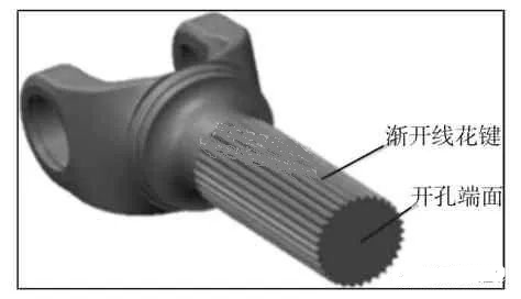
The spline shaft is reduced from the original 32 teeth to 30 teeth, and the spline shaft fork is hollowed out.
The design removes a cylinder with chamfer at the front end of the spline shaft body, and by analyzing the stress, deformation and quality of the spline shaft fork under different diameters and heights of the cylinders, it is finally determined that the diameter of the cylinder is 50mm, the height is 164mm, and the front end is 120 chamfered, so that the optimized spline fork is shown in Fig. 11.
The optimized spline fork is shown in Fig. 11. The maximum stress and displacement of the optimized spline fork is less than that of the pre-optimized fork and is within the safe range, the mass is reduced from 19.164kg before optimization to 16.433kg after optimization, which is a weight reduction of 2.731kg. the graph of the optimized cardan fork is shown in figure 12. the mass is reduced from 10.30kg before optimization to 16.433kg after optimization.
The mass decreases from 10.304kg before optimization to 9.512kg after optimization, with a weight reduction of 0.792kg.
4 Conclusion
The topology optimization design method, combined with Creo and ANSYS Workbench software, is used to carry out a lightweight design study of heavy-duty vehicle drive shafts.
In order to verify the validity of the simulation model, firstly, the static mechanical analysis was carried out on the parts before optimization, and the model was corrected and calibrated.
Then the topology optimization analysis is carried out on the modified finite element model.
According to the analysis results, the relevant dimensions of the model are reduced and optimized by combining with the actual structure of the parts, manufacturing and assembly process, so that the mass of the flange yoke is reduced from 9.23kg before optimization to 6.874kg after optimization, which is a reduction of about 25.5%; the mass of the spline yoke is reduced from 19.16kg before optimization to 16.43kg after optimization, which is a reduction of about 14%; and the mass of the splined yoke is reduced from 19.16kg before optimization to 16.43kg after optimization.
The mass of the spline shaft yoke is reduced from 19.16kg before optimization to 16.43kg after optimization, a reduction of about 14.2%; the mass of the universal joint fork is reduced from 10.304kg before optimization to 9.512kg after optimization, a reduction of about 7.7%; and the overall weight of the rear drive shaft is reduced by 8.235kg, a reduction of about 10%.
Although the concentrated stress of the parts increases while reducing the weight, the design of the parts meets the engineering requirements after the safety coefficient check and the verification of the driveshaft bench test.
The optimized product operates well in the actual project, which meets the expected optimization design goal and achieves the purpose of lightweight design.
The optimized design is in line with the concept of lightweight, which reduces the manufacturing cost of the driveshaft, and verifies the feasibility of topology optimization method in the field of lightweight design, which provides a useful reference and available tools for the lightweight design of automotive parts.