
Abstract: The driveshaft/propshaft is a key component that affects the NVH performance of the whole vehicle, in order to reduce the vibration of the car and improve the ride comfort, the causes of rotor vibration are analyzed using a combination of mathematical modeling and theoretical analysis, the vibration model of the driveshaft is established, and the factors affecting the vibration of the driveshaft are analyzed.
The results show that the unbalanced quality of the drive shaft is the root cause of its vibration; the steady state centrifugal force frequency of the drive shaft is the same as the intrinsic frequency of the system and the relative damping coefficient of the drive shaft is too small, which is easy to cause system resonance.
The results provide a theoretical reference for improving the dynamic balancing accuracy of the driveshaft and thus enhancing the NVH performance of the whole vehicle.
Keywords: drive shaft: dynamic balancing; vibration characteristics: analysis
With the popularization of automobiles in life, people’s requirements for automobile handling stability and ride comfort are increasing.
Therefore, the NVH problem of automobiles has become the focus of attention of experts and scholars in colleges and universities as well as engineers in enterprises.
The vibration of automobile transmission system has always been one of the concerns in the research and development process, and as the core component of the transmission system, the driveshaft is very easy to cause automobile vibration in the process of high-speed rotation.
In order to solve the transmission shaft vibration problem, the article from the causes of transmission shaft vibration, establish its vibration model, and analyze the factors affecting vibration, for the development and design of the transmission shaft to provide theoretical reference.
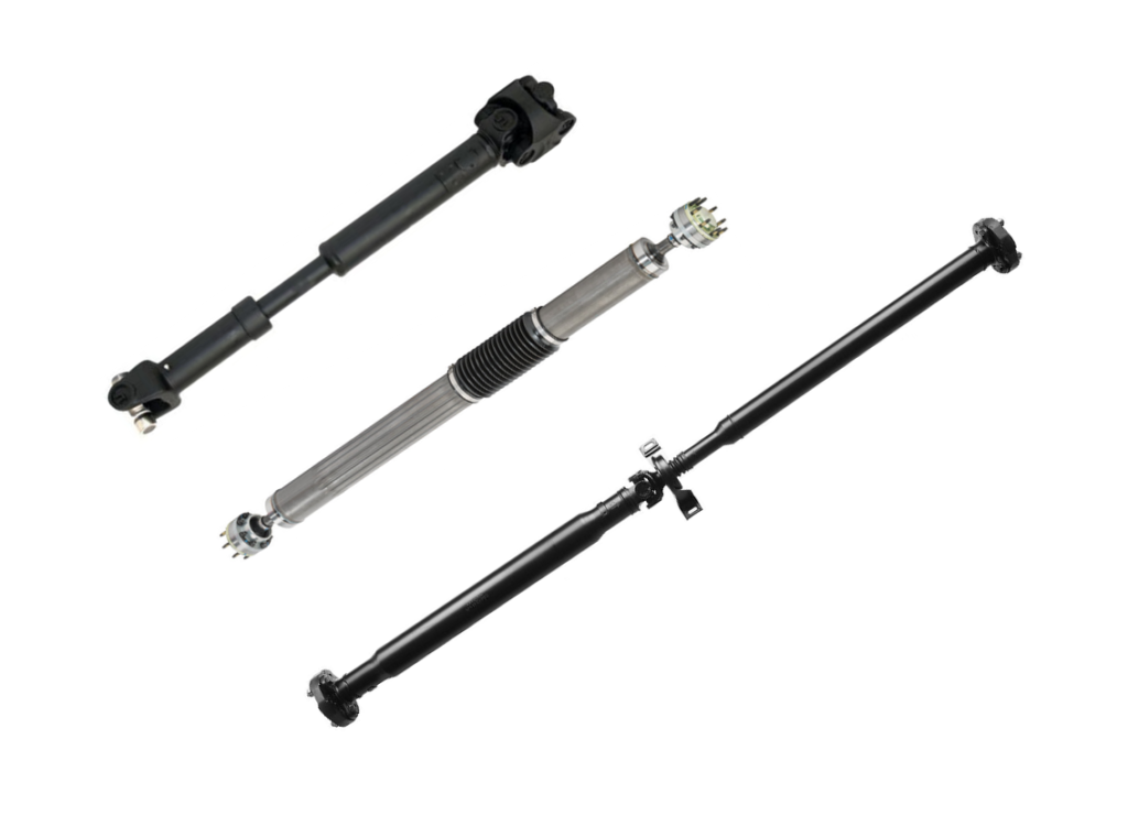
1 Drive shaft/Prop shaft structure
Drive shaft/prop shaft is a key component of the transmission system, which plays a role in transmitting power, torque and motion in the process of automobile driving.
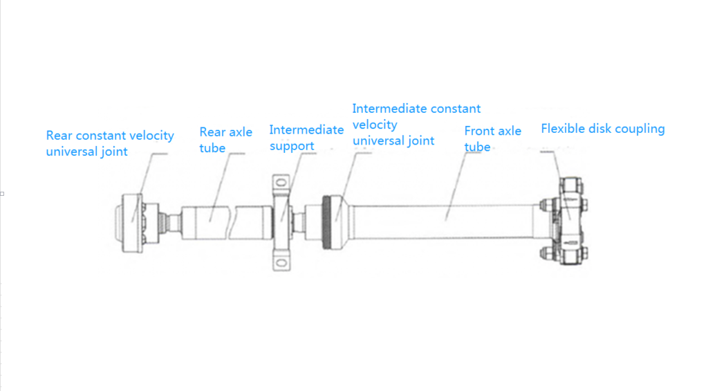
In the driveshaft/propshaft assembly, the rear constant velocity universal joint is connected to the rear main reducer, the intermediate support is fixed with the body through bolts, and the flexible disk coupling is connected to the splitter.
Among them, the intermediate support and the flexible disk coupling are rubber parts, which have the function of absorbing shock loads and attenuating torsional vibrations in the driveline.
The main components of the rear axle driveshaft assembly of a certain model are shown in Figure 1.
2 Rotor dynamic unbalance causes vibration
Ideally, whether at rest or in motion, the rotor is in equilibrium, the rotor movement is in equilibrium in the radial analysis of the diagram, shown in Figure 2.
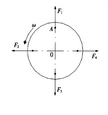
In Fig. 2, A is any point with mass, and its centrifugal force is calculated according to equation (1).
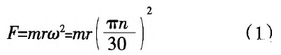
Where: m–4 points mass, kg;
Guang–_4 points from the center of rotation distance, mm;
∞–rotor rotation angular velocity, rad/s;
n–Rotor rotation speed, r/min.
In the radial plane, when the mass inside the rotor is uniformly distributed, due to the rotational speed is equal, then the vector sum of each point in the radial plane is zero, i.e.:

Where: F – sum of centrifugal force at each point, N;
F., F:, ⋯, F, – a centrifugal force at each point in the radial plane, N.
However, in the actual process, the rotor operation, due to the manufacturing process of mechanical processing is not accurate, material wear and material uneven and other reasons M, resulting in uneven mass distribution of the rotor around the center of rotation, resulting in the centrifugal force vector sum at each point is not zero.
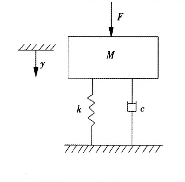
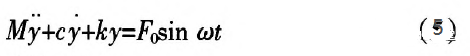
According to the force translation theorem, the centrifugal force at each point can be shifted to point B, as shown in Fig. 3. The mass at point B (black) is the amount of unevenness of the rotor mass, and the rotor centrifugal force is caused by the mass imbalance of the rotor, so that the centrifugal force (Fo) at point B is the rotor centrifugal force as shown in Equation (3).
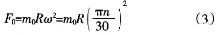
Where: R–Distance of day point from the center of rotation, mm.
In the driveshaft shown in Figure 1, the centrifugal force rotates with the driveshaft and is transmitted to the intermediate support through the bearing, which causes the support reaction force of the intermediate support, however, the intermediate support is forced to be fixed to the body, so the centrifugal force of the driveshaft makes the driveshaft and the intermediate support form a system forced vibration.
From the above analysis, it can be seen that the root cause of the drive shaft vibration is its own mass imbalance.
Due to the actual machining accuracy errors are inevitable, so the mass imbalance of the drive shaft can only be controlled within a certain range, it is impossible to eliminate 100% is-10l.
3 Drive shaft/Prop shaft vibration model and analysis
The centrifugal force caused by the mass imbalance of the drive shaft is equivalent to a periodic disturbance force acting on the whole system, which is stimulated by the constant high-speed rotation of the engine, so even if there is an intermediate support and flexible disk coupling to absorb some of the energy, the system vibration caused by the periodic disturbance force will not be attenuated.
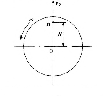
Figure 4 below illustrates the vibration model of a one-degree vibration system of a drive shaft with the application of springs, drive shaft mass and damping system.
Since the external excitation is periodic, the disturbing force can be considered as a sinusoidal or cosinusoidal simple harmonic excitation force and calculated according to equation (4).

The differential equation of a single degree vibration system under the action of sinusoidal simple harmonic excitation force is shown in equation (5).
Where: coercion–drive shaft mass, kg; displacement of the drive shaft in the vertical direction, ram;
c – drive shaft damping, N-s/mm;
After – spring stiffness, N / mm.
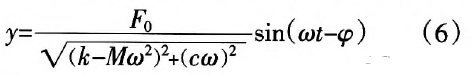
Solve Eq. (5) to obtain the steady state solution of the forced vibration equation, as shown in Eq. (6).
Steady state amplitude, as shown in equation (7).

From equation (6) and equation (7), it can be seen that under the action of simple harmonic excitation force, the forced vibration of the drive shaft is also simple harmonic vibration; Y is proportional to the centrifugal force of the drive shaft; due to the existence of damping, the phase angle of the forced vibration is φ-angle different from the phase angle of the excitation force.
In order to further understand the relationship between the amplitude of the drive shaft in steady state and its influencing factors, the following physical quantities and relational equations are introduced:

Where: p – the intrinsic circular frequency of the drive shaft in undamped vibration, depending on the
on the system characteristics, independent of the initial conditions;
σ – the ratio of the steady state centrifugal force frequency of the drive shaft to the intrinsic frequency of the system
σ – the ratio of the steady state centrifugal force frequency of the drive shaft to the intrinsic frequency of the system;
p – the relative damping coefficient of the drive shaft, i.e., the ratio between the actual damping and the critical damping that can induce the system vibration.
p – relative damping coefficient of the drive shaft, that is, the actual damping and can lead to the system vibration of the critical damping ratio;
y0 – the maximum static displacement of the drive shaft at rest;
Kuang – drive shaft amplitude in the steady state and the maximum static displacement of the stationary state
The ratio of the maximum static displacement at rest.
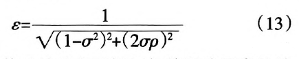
By the formula (7) to (12) can be obtained:
In order to intuitively understand the relationship between the amplitude of the drive shaft at steady state and its influencing factors, Matlab software is used to simulate the vibration model, and the amplitude-frequency curve of the drive shaft is obtained by organizing the data, as shown in Figure 5.
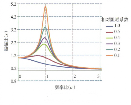
From Fig. 5, it can be seen that
1) When p=1.0, the steady state amplitude of the drive shaft shows a decreasing trend, because the actual damping of the drive shaft does not reach the critical conditions of the system vibration.
2) When p<1, the magnitude of stare has a large influence on the steady state amplitude of the drive shaft: a. When or tends to 0, that is, the drive shaft speed is 0, its amplitude is the maximum displacement at rest; b. When 0 < σ < 1, as or increases, the steady state amplitude increases; when σ > 1, as σ increases, the steady state amplitude decreases until zero.
c. When σ=l, the drive shaft steady-state amplitude in the corresponding state is the largest, because the rotation frequency of the drive shaft and the system’s intrinsic frequency is equal, thus the system resonance phenomenon.
3) Regardless of the value of P, when σ increases to close to 3, y is reduced to o. This is because the direction of the drive shaft steady-state centrifugal force frequency changes too quickly, the drive shaft is too late to follow, and almost stop moving.
It can be seen that, in order to avoid resonance, when designing and developing the drive shaft, the design rotation frequency of the drive shaft should be made to avoid its own inherent frequency; at the same time, the damping of the drive shaft should be controlled so that it is greater than or equal to the critical damping.
4 Conclusion
1) Through the analysis of the causes of driveshaft vibration, it is obtained that the mass imbalance of the driveshaft is the root cause of automobile vibration;
2) The conditions of system resonance are obtained by analyzing the established transmission shaft vibration model;
3) In order to avoid system resonance, when designing and developing the drive shaft, the design rotation frequency of the drive shaft should avoid the intrinsic frequency of the system;
4) When the actual damping of the drive shaft is greater than or equal to the critical damping of the system vibration, it will not cause the system resonance regardless of the frequency.
