
Abstract: Transaxle is a key transmission component of commercial vehicle powertrain, which has an important impact on the NVH performance of the whole vehicle.
The article carries out modal CAE and experimental research for a commercial vehicle transaxle, and the C AE analysis and experimental results show that the NVH modal performance of transaxle of this commercial vehicle meets the target.
1 Introduction
With the rapid development of the national economy, people’s living standards are improving, the sales of commercial vehicles have also been rapid development, at the same time, people for the vehicle NVH quality requirements are also more and more high.
Transaxle as an important part of the automobile transmission system, in the actual working process, if by itself or other external excitation, will produce vibration and noise, not only affects the comfort of the car, the more serious will cause the drive shaft and the transmission and drive axle connected to the drive shaft will produce damage, and even affect the safety of the driving position [1-3].
Therefore, the study of driveshaft NVH modal performance has important value and significance.
In this paper, the research stems from a commercial vehicle newly developed driveshaft system, need to ensure that its NVH modal performance to meet the requirements of the design goals, through the finite element method, based on Nastran software, a commercial vehicle driveshaft CAE modal analysis, combined with the modal test test, CAE analysis results and test results show that the commercial vehicle driveshaft NVH modal performance to avoid the engine idling resonance frequency, performance meets the target.
2 Drive Shaft CAE Modal Analysis
2.1 Drive Shaft FEA Model
In this paper, the finite element software Hyperworks is used to model the drive shaft of a commercial vehicle, the mesh size is 4mm, the corresponding material is 40Cr, the axial dynamic stiffness of the rubber at a frequency of 35Hz is 220N/mm, the radial dynamic stiffness is 270N/mm, and the model has a mass of 27.3kg, and the finite element model is shown in Figure 1.

Fig. 1 FEA model of a commercial vehicle driveshaft
2.2 CAE free modal analysis of driveshaft
This paper analyzes the free modes of a commercial vehicle driveshaft, the CAE analysis results are shown in Figure 2, the first-order Z-direction bending mode frequency is 244.5Hz, the second-order Y-direction bending mode frequency is 246.9Hz.
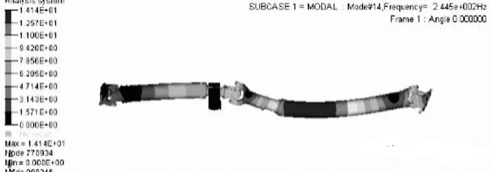
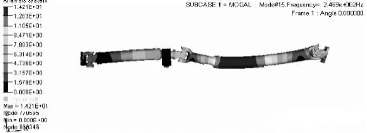
Figure 2 CAE free modal analysis results of the driveshaft
2.3 CAE Constrained Modal Analysis of Drive Shaft
In this paper, the constrained modal analysis is carried out on the driveshaft of a commercial vehicle, constraining the motor output shaft bearing position and the rear axle output shaft bearing support position with full degrees of freedom, and at the same time constraining the intermediate suspension bracket and the frame fixed mounting holes with full degrees of freedom, and obtaining the constrained modal analysis results of the driveshaft as shown in Fig. 3, of which the first-order rear axle Z-direction bending modal is 236.8 Hz, the second-order Y-direction bending modal is 239.4 Hz. 239.4Hz.
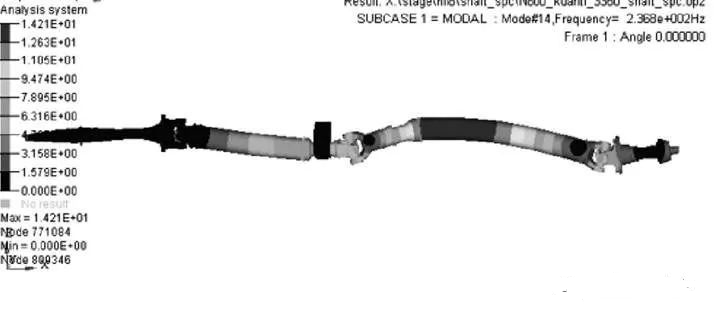
Fig. 3 CAE constrained modal analysis results of the driveshaft
2.4 CAE bench state modal analysis of driveshaft
In this paper, a commercial vehicle driveshaft is subjected to bench modal analysis, and the constraint boundary conditions are shown in Fig. 4, which constrain the full degree of freedom at the bolt connection point of the intermediate bracket and the frame, and constrain the full degree of freedom at the bolt holes of the cross universal joints at both ends.
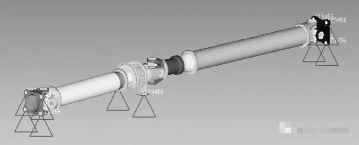
Figure 4 Boundary conditions for CAE modal analysis of driveshaft frame
In this paper, according to the above boundary conditions, the CAE modal analysis results of the driveshaft in the bench state are obtained as shown in Fig. 5, in which the first-order rear axle Z-direction bending mode frequency is 219.4 Hz, and the second-order rear axle Y-direction bending mode frequency is 221.8 Hz.
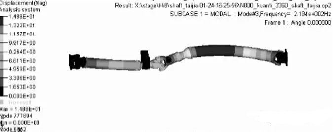
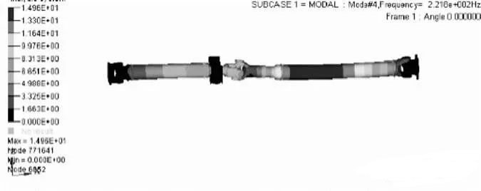
Fig. 5 CAE modal analysis results of driveshaft frame
3 Drive Shaft Modal Test Analysis
3.1 Drive shaft free modal test analysis
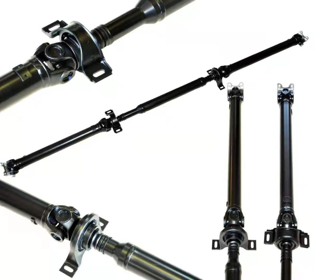
In this paper, the free modal test was conducted on a commercial vehicle driveshaft system, as shown in Figure 6. The length of the driveshaft is 1.5m, the mass is 27.6kg, and the diameter of the driveshaft is 10mm.
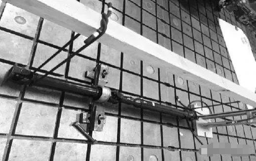
Fig. 6 Free modal test of driveshaft
The test was conducted according to the above test boundary conditions, and the free modal test results of the drive shaft in Fig. 7 were obtained, with the first order frequency of 249 Hz, the vibration pattern of which was the Z-direction S-bending mode, and the second order frequency of 479 Hz, the vibration pattern of which was the Y-direction W-bending mode.
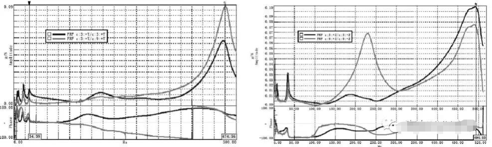
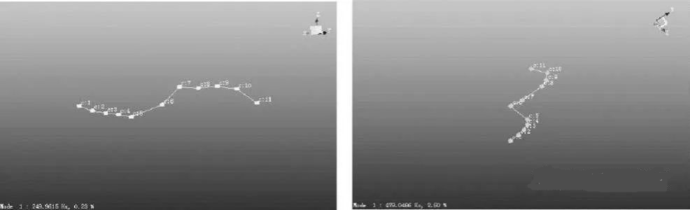
Fig. 7 Free mode test results of driveshaft
3.2 Analysis of Drive Shaft Bench Restrained Modal Tests
In this paper, the LMS signal acquisition equipment is used to conduct a bench constrained modal test on the driveshaft of a commercial vehicle by means of a force hammer, as shown in Fig. 8, and the sample size of the test is two, and the vibration pattern and frequency of the driveshaft are recorded during the test.
In this paper, according to the above bench constraint boundary conditions, the drive shaft modal test was carried out, and the test results were obtained as shown in Fig. 9. Under the torque of 0Nmm, the first-order bending frequency of the drive shaft is 240Hz, and the second-order frequency is 438Hz, which is well aligned with the CAE analysis and meets the target of more than 150Hz.
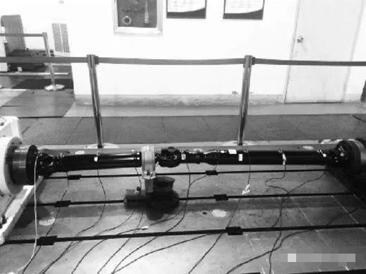
Figure 8 Drive shaft bench constrained modal test
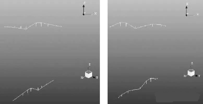
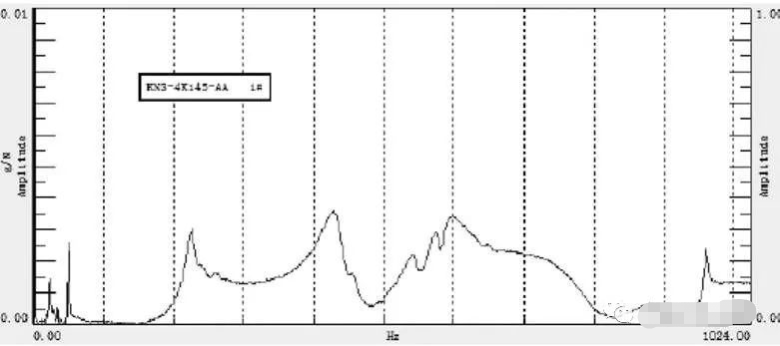
Fig. 9 Drive Shaft Bench Restrained Modal Test Result
3.3 Modal test analysis of driveshaft under vehicle condition
In this paper, the modal test of a commercial vehicle driveshaft under the vehicle state is conducted, and the modal test results are shown in Fig. 10, in which the first-order Z-direction bending mode is 174.6 Hz, the second-order Y-direction bending mode is 239.4 Hz, and the third-order Z-direction bending mode is 256.1 Hz.
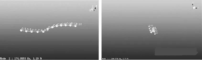
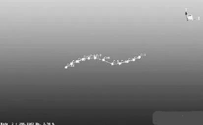
Fig. 10 Modal test results of the driveshaft under the whole vehicle condition
4 Conclusion
Based on NASTRAN finite element simulation and analysis software, this paper carries out CAE free mode, constrained mode and modal analysis under bench state for a commercial vehicle driveshaft, and meanwhile combines with the modal test to carry out the driveshaft free mode test, modal test under bench state and modal test under the whole vehicle state, and the results of the CAE analysis and the bench test show that the driveshaft of this commercial vehicle avoids the engine idling frequency and meets the design requirements. engine idling frequency and meets the design objectives.