
Abstract: Through the material performance evaluation and product CAE analysis, the carbon fiber composite shaft tube molding is completed by the winding method molding process, and the riveting and sticking connection technology realizes the reliable connection between the shaft tube and the metal universal joints, and the developed carbon fiber composite driveshaft combines the original two segments of tandem connection into one segment, eliminates a pair of metal universal joints, and reduces the mass by more than 40%. The results of bench test show that the static torsional strength, torsional fatigue life, critical speed and other performance indexes of the product meet the requirements of the national automotive industry standard QC/T 29082-2019, “Automotive Drive Shaft Assembly Technical Conditions and Bench Test Methods”.
Keywords: carbon fiber composites, driveshaft, winding method, riveted and bonded connection.
1 Introduction
Carbon fiber (CF) is a new type of fiber material with high strength and high modulus containing more than 90% carbon. Carbon fiber reinforced resin matrix composites (CFRP) are composites with carbon fiber as reinforcement and resin as matrix.The application of CFRP can reduce the mass of automobile body and chassis by 40% to 60%, which is equivalent to 1/3 to /1/6 of the mass of steel structure [1]. The use of CFRP’s high specific strength and high specific modulus can effectively increase the length of the drive shaft, reduce redundant universal joints, reduce the mass, reduce noise and improve vibration resistance. Foreign countries have begun the study of carbon fiber composite drive shafts since the 1970s, and a lot of work has been done in the structural design, molding process, and connection of carbon fiber composite drive shafts. Domestic scholars have done research on the structural design of the shaft body, static characteristics, dynamic characteristics of the composite drive shaft, and obtained a series of conclusions. Such as unidirectional layup direction close to 0 °, 45 ° and 90 °, the torsional strength of the structural components is higher, and torsional strength with the increase in the wall thickness of the structural components and increase; increase 40 ~ 70 ° layup can improve the torsional stiffness of the components; symmetric layup is more conducive to the parts to withstand the torque than with the asymmetric layup; composite driveshafts are better than the steel, aluminum alloy drive shafts, and the amplitude of main resonance is small, etc.[2]. The main resonance amplitude is smaller than that of steel and aluminum alloy drive shafts. This paper describes the development of corresponding carbon fiber composite products using a steel drive shaft with a tube diameter of Φ89 mm as a target part and the verification of its reliability and lightweight effect.
2 Design of Carbon Fiber Drive Shaft
2.1 Tube material selection
Transmission shaft is a key component for transmitting engine power, in order to ensure the required performance and lightweight target, 12KT700 carbon fiber plus epoxy resin is selected as the transmission shaft tube material. In accordance with GB/T 1458-2008 “Test Method for Mechanical Properties of Fiber Winding Reinforced Plastic Ring Specimens” [3], the basic performance test of the material is completed. The NOL ring is made by the cylinder cutting method in wet winding, and the carbon fiber is wetted with resin and then wrapped into a cylinder with a cylinder mandrel on a winding machine, and then cured, processed on the outer surface, demolded, and cut to produce the ring specimen. The tensile test specimen is a ring-shaped specimen with an inner diameter of 150 mm, a thickness of 1.5 mm and a width of 6 mm. The interlaminar shear test specimen was cut from the same NOL ring with a thickness of 3 mm and a length of 18-21 mm, and then an electronic universal testing machine was used to test the tensile modulus, tensile strength and interlaminar shear strength of the NOL ring. The laboratory temperature was 23°C ± 2°C and the test rate was 1 mm/min. The test results are shown in Table 1.
Table 1 Properties of NOL ring specimens of carbon fiber-epoxy resin materials
Note: “-” means that the material does not have this property.
Comparison of the test data with the structural steel data shows that the specific strength of the unidirectional epoxy-based carbon fiber composite material is about 5 times that of steel, and the specific modulus is about 3 times that of steel, except that the interlaminar shear strength of the material is significantly lower than the tensile strength of the material, and the anisotropy is significant.
2.2 Structural design of composite drive shaft/prop shaft
Automotive drive shaft is a rotary motion component, if the composite material drive shaft torsional stiffness and modulus is insufficient, it will lead to excessive deformation at the end of the shaft body, causing intense vibration of the mechanical system, resulting in the mechanical system can not operate normally. Therefore, the reasonable design of composite drive shaft torsional performance is very critical. With the development of computer technology and the gradual improvement of the theory of composite materials, there are many CAE software to support the performance analysis of composite materials and part design. For example, ANSYS, ABAQUS, LS-DYNA and so on. Advanced computer-aided technology reduces the labor force and helps engineers to complete the product design, analysis and manufacturing preparation [4].CFRP has the characteristics of anisotropy, non-homogeneity and low interlaminar shear, and its design can generally be adopted from the classical composite laminate theory [5]. For carbon fiber composite drive shafts, the factors affecting their torsional properties are mainly the outer diameter of the shaft tube, the winding angle and the winding thickness [6].
2.2.1 Structural design and technical requirements of target parts
Carbon fiber composites have the characteristics of light weight, high strength and high modulus, which can effectively improve the critical speed of the drive shaft, so the composite automotive driveshaft developed is proposed to combine the existing two segments of the tandem metal driveshaft (Fig. 1) into a single one, and eliminate a pair of redundant universal joints and intermediate shaft supports between the two segments of the metal driveshaft.
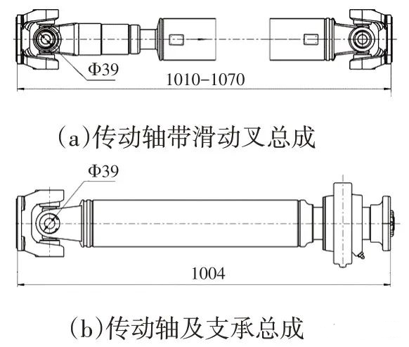
Figure 1 Metal driveshaft
Referring to the technical conditions of the metal drive shaft, the basic technical parameters of the composite drive shaft are preliminarily determined as follows.
a. The total length of the drive shaft is 1,950-2,070 mm, and the length of the CFRP shaft tube is 1,520 mm;
b. The outer diameter of the CFRP shaft tube is ≤120 mm, and the inner diameter is 105 mm;
c. The lug diameter is 39 mm, the rated torque is 3 400 N-m, the torsion angle of the drive shaft under this torque is ≤10°, and the safety factor n>2;
d. Working speed of 1 400 ~ 2 100 r / min, the maximum speed of 3 440 r / min, critical speed ≥ 3 750 r / min;
e. When the driveshaft is placed horizontally, the universal joint angle is 0°, and the others need to meet the provisions of the national automotive industry standard QC/T 29082-2019 Technical Conditions and Bench Test Methods for Automotive Driveshaft Assemblies [7].
2.2.2 Simulation analysis
Based on the material properties and basic technical parameters of the drive shaft, the composite automotive drive shaft design program is analyzed by computer simulation. The drive shaft consists of metal connectors and carbon fiber shaft tube parts, of which the metal connectors are composed of splines, flange forks, cross shafts, etc. The material of metal joint is 40Cr steel, the wall thickness of the connection area with the tube body is 4.2 mm, machined manufacturing and tempering treatment, the yield strength of σb after tempering is ≥ 900 MPa, the number of models as shown in Figure 2.
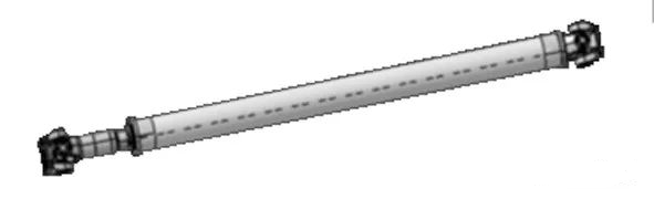
Fig. 2 Carbon fiber composite drive shaft number molds
CFRP shaft tube layup design, the angle of 0 °, ± 45 °, 90 ° respectively layup, as shown in Figure 3, the material for the T700 carbon fiber and epoxy resin matrix.
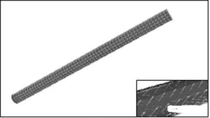
Fig. 3 Schematic of fiber layup and direction
After setting the boundary constraints, considering the role of torque, through the adjustment of the diameter of the shaft tube, the number of layers and angle, the use of finite element method to verify the strength of the drive shaft, the results of the composite shaft tube buckling coefficient of 6.7, 6,800 N-m torque torsional deformation of the cloud as shown in Fig. 4, the composite tube end needs to be locally strengthened, the other parts of the factor of safety are to meet the requirements.
Since the premise of the saturation vapor pressure analysis of the components in the alloy is to consider the component metals in a pure material state, it has certain limitations. For actual binary or poly alloys, different alloy components will have an impact on the actual vapor pressure of each metal component, which in turn will affect the actual separation effect of the alloy separated by vacuum distillation. Considering this factor, the separation coefficient β can be utilized to determine the separation possibility of the components in the alloy. The separation coefficient is calculated in equation (2).
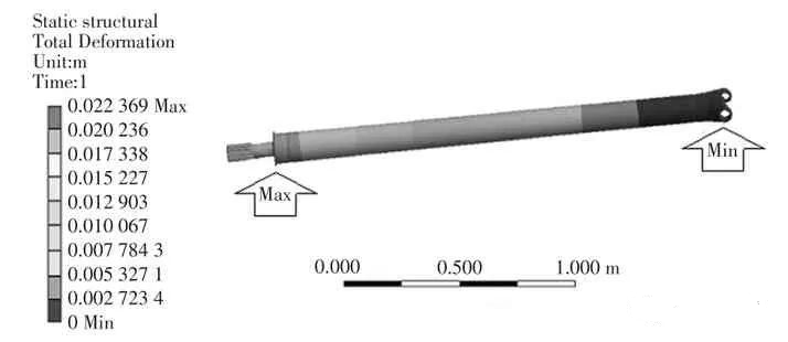
Fig. 4 Cloud diagram of torsional deformation for 6 800 N-m torque
The intrinsic frequency in free mode is about 77 Hz (Fig. 5), and the predicted critical speed is up to 4 600 r/min, which meets the design requirements.
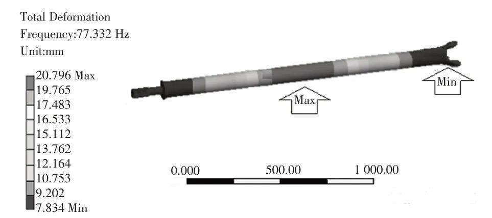
Fig. 5 Intrinsic frequency cloud diagram
2.2.3 Connection design
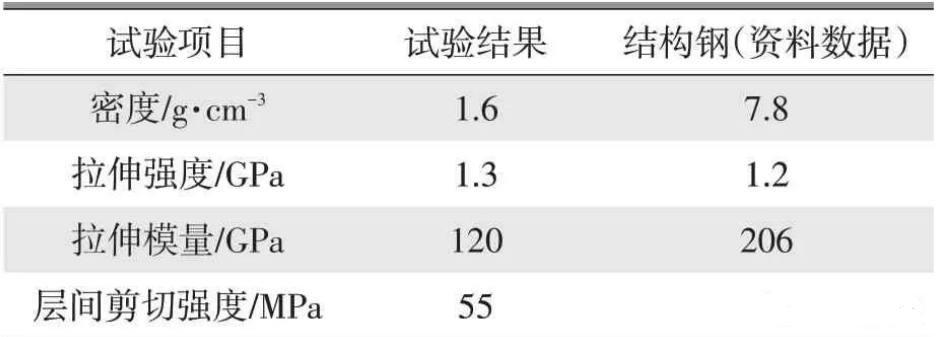
The connection design is shown in Figure 6, the metal joint and CFRP pipe body are connected by mechanical and epoxy resin adhesive. The metal connector and the tube body are tightened by winding the gap fit, and both ends of the tube body are anchored by rivets, the connection width is about 70 mm, the rivet diameter is 3.5 mm, and 3 rows are set at each end. The length of rivets is adapted to the thickness of the winding overlay at both ends of the pipe body, and the surface should not leak out.
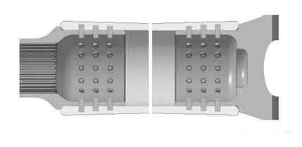
Fig. 6 Schematic diagram of the connection between carbon fiber shaft tube and metal parts
3 Manufacture of carbon fiber drive shaft/prop shaft
The more typical molding process for shaft parts at present is the wet winding process, as shown in Fig. 7. Wet winding is to wind the fiber clusters directly onto the mandrel under tension control after they are impregnated with glue.
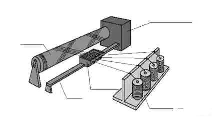
Fig. 7 Schematic diagram of wet winding of carbon fiber axial tube
The advantages of wet winding are low cost, dense product, good parallelism of fiber arrangement, resin glue on the fibers, which can reduce fiber abrasion, and high production efficiency; the disadvantages are large waste of resin, poor operating environment, glue content and quality of finished product are not easy to control, and fewer varieties of resin are available for wet winding.
3.1 Process
Forming equipment includes winding machine (CRJ-12 CNC winding machine), fiber impregnation, export, tension control equipment, drying equipment and so on.
Wet winding process flow is resin paste preparation, fiber material pretreatment, guide opening, wetting, traction, adjusting tension, four-axis automated winding machine technical parameters input and equipment preparation, mandrel and both ends of the metal parts installation, centering, opening the core axis slowly rotating, the guide wire head along the parallel direction, winding is completed, pumping the core (also can not be pumped), the parts are sent to the oven for curing.
3.2 Carbon fiber composite material drive shaft/prop shaft trial parts
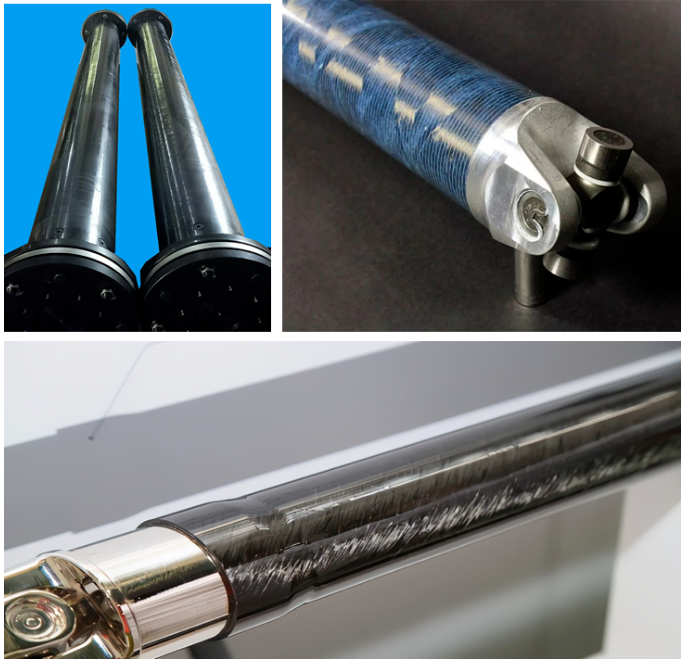
Carbon fiber composite material drive shaft trial parts, as shown in Figure 8.
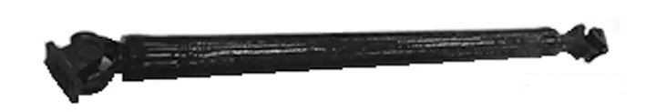
Figure 8 Carbon fiber composite drive shaft trial parts
Carbon fiber composite drive shaft trial parts basic data and steel drive shaft comparison, the results are shown in Table 2.
Table 2 Comparison of basic data of CFRP drive shaft trial parts with steel drive shafts
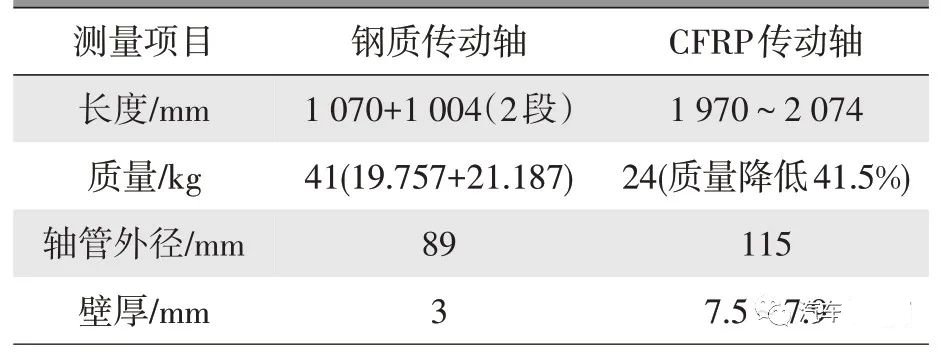
Through the comparison of data in Table 2, it can be seen that the use of carbon fiber composite shaft tube can be 2 segments of about 1 m long drive shaft into 1 segment of 2 m long drive shaft, due to the elimination of a pair of metal universal joints, the quality reduction reaches 41.5%. However, in order to meet the required static torsional strength and critical speed requirements, the diameter of the shaft tube is increased by 28%, and the design parameters should be further optimized when constrained by space conditions.
4 Test
4.1 Test basis and project
According to QC/T 29082-2019 [7], the CFRP drive shaft test items, test methods and technical indicators are determined. The main test items are critical speed, static torsional strength, torsional fatigue and intrinsic frequency; the main test equipment is as follows.
a. NDS-100 static torsion testing machine (Figure 9);
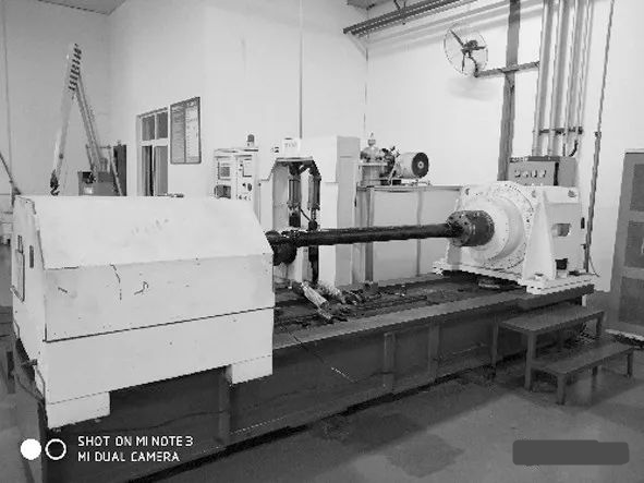
Figure 9 NDS-100 type static torsion testing machine
b.TSPH-1 drive shaft critical speed test rig;
c.Intrinsic Frequency Test Stand;
d. TST-3 drive shaft torsional fatigue test rig, etc.
4.2 Test results and discussion
The test results are shown in Table 3, and the test conclusions derived from Table 3 are as follows.
Table 3 Main performance test results of carbon fiber composite driveshafts
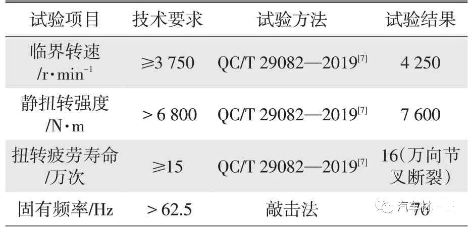
a.Through the bench test, the carbon fiber composite driveshaft products developed, static torsional strength, torsional fatigue life, critical speed and other performance indicators meet the requirements of the national automotive industry standard QC/T 29082-2019 [7], indicating that the adopted design and process technology program is feasible;
b. The computer design simulation results are basically consistent with the actual test results;
c.The static torsional strength and torsional fatigue life test are terminated in the destruction of metal parts, indicating that the strength and life of the carbon fiber composite axle tube body and connecting parts are better than the metal parts at both ends of the drive shaft.
5 Lightweight effect and cost analysis
Through the above work, it can be seen that the carbon fiber composite drive shaft configured with steel universal joints at both ends can achieve the lightweight effect of quality reduction of more than 40%, and analyze that if aluminum alloy universal joints are used at both ends, the lightweight effect can be further enhanced to about 60%, so the carbon fiber composite drive shaft still has great potential for application. With the further maturity of design simulation, connection technology and manufacturing technology, the commercialization of CFRP drive shafts can be expected in the future.
The cost of the carbon fiber composite drive shaft developed by the calculation is about 4 times of the steel metal drive shaft (about 1.8 times of the all-aluminum alloy drive shaft). Total cost, carbon fiber accounted for 40%, resin accounted for 18%, metal parts accounted for 4.2%, process and other costs accounted for 38%, the total cost of composite materials accounted for nearly 60%, followed by process costs. The current market price of carbon fiber composites is relatively high, and the cost is one of the main factors restricting the application of carbon fiber composite drive shafts. The use of carbon fiber / glass fiber layup technology with different mixing ratios is expected to reduce the cost of about 10% to 30%, the performance has to be further experimental verification, with the development of low-cost carbon fiber composites as well as rapid prototyping technology continues to improve, carbon fiber composite drive shaft application bottlenecks will be able to break through.
6 Conclusion
The carbon fiber composite shaft tube molded by winding method realizes the reliable connection between the shaft tube and the metal universal joint through the adhesive rivet connection technology, and the developed drive shaft greatly reduces the structural quality while combining the original two metal drive shafts into one, realizing the integration of parts, and improving the vibration-resistant performance. Due to the elimination of a pair of metal universal joints, the mass is reduced by more than 20 kg, and the product’s static torsional strength, torsional fatigue life, critical speed, and other performance indicators meet or exceed the requirements of the national automotive industry standard QC/T 29082-2019 [7].
At this stage, the material and process cost is one of the main factors restricting the wide application of carbon fiber composite driveshafts. Related low-cost material process technology development is becoming a research hotspot.